In fluid systems, few topics are as fundamental—and as frequently misunderstood—as the relationship between flow و الضغط in a pipe. Engineers often hear statements like “higher pressure means higher flow” أو “low pressure causes low flow”, yet in real pipeline systems, the relationship is far more nuanced.
Accurate understanding of pipe flow vs pressure is essential for designing pipelines, selecting pumps and compressors, choosing flow meters, diagnosing system problems, and ensuring safe, efficient operation across industries such as oil & gas, water treatment, chemical processing, energy, and manufacturing.
جدول المحتويات
What Is Pressure?
الضغط is the force exerted by a fluid per unit area on the walls of a container or pipe.
P=F/A
أين:
- PPP = pressure
- FFF = force
- AAA = area
Common Units of Pressure
- Pascal (Pa)
- bar
- psi (pounds per square inch)
- MPa
Types of Pressure in Pipe Systems
- Static pressure – pressure at rest
- Dynamic pressure – pressure associated with fluid velocity
- Differential pressure (ΔP) – pressure drop between two points
- Gauge pressure – pressure relative to atmosphere
- Absolute pressure – pressure relative to vacuum
In pipelines, pressure serves primarily as the driving force that overcomes resistance and moves fluid from one point to another.
What Is Flow?
Flow describes how much fluid moves through a pipe over time. Typically, flow can be expressed in terms of volume flow or التدفق الكتلي.
Volume flow refers to the volume of fluid flowing through a pipe cross-section per unit time, usually expressed in units such as cubic meters per second (m³/s) or cubic meters per hour (m³/h).
Mass flow refers to the mass of fluid flowing through a pipe section per unit time, usually expressed in units such as kilograms per second (kg/s).
What Is Pipe Diameter?
Pipe diameter determines the cross-sectional area available for flow and is one of the most influential variables in pipeline behavior.
Why Pipe Diameter Matters
- Larger diameter → lower velocity for the same flow
- Lower velocity → lower friction losses
- Small diameter changes can cause large pressure drop changes
In fact, pipe diameter has a non-linear effect on pressure loss, making it a critical design variable.
Pipe Diameter Conversion Table
| NPS (Nominal Pipe Size – in Inches) | DN (Nominal Diameter – in Millimeters) |
|---|---|
| 1/8″ | 6 |
| 1/4″ | 8 |
| 3/8″ | 10 |
| 1/2″ | 15 |
| 3/4″ | 20 |
| 1″ | 25 |
| 1 1/4″ | 32 |
| 1 1/2″ | 40 |
| 2″ | 50 |
| 2 1/2″ | 65 |
| 3″ | 80 |
| 3 1/2″ | 90 |
| 4″ | 100 |
| 5″ | 125 |
| 6″ | 150 |
| 8″ | 200 |
| 10″ | 250 |
| 12″ | 300 |
| 14″ | 350 |
| 16″ | 400 |
| 18″ | 450 |
| 20″ | 500 |
| 24″ | 600 |
Note: NPS and DN are nominal sizes; actual pipe OD/ID may vary by standard and schedule.
Importance of Monitoring Pipeline Pressure and Flow
Monitoring both pressure and flow—not just one—is essential for system performance and safety.
Why Pressure Monitoring Is Critical
- Detects blockages or fouling
- Prevents over-pressure damage
- Ensures pump and compressor protection
- Indicates leaks or valve malfunctions
Why Flow Monitoring Is Critical
- Confirms actual throughput
- Supports custody transfer and billing
- Enables process control and batching
- Detects production losses
Why Pressure Alone Is Not Enough
High pressure does not guarantee high flow. A blocked or closed pipeline can show high pressure but zero flow. Likewise, high flow may exist at relatively low pressure if resistance is low.
Relationship Between Flow and Pressure
The relationship between flow and pressure in a pipe is governed by fundamental physical laws. While many simplified explanations exist, in engineering practice three core relationships matter the most:
- Bernoulli’s Equation – energy conversion between pressure and velocity
- Darcy–Weisbach Equation – pressure loss due to friction (real pipelines)
- Poiseuille’s Law – flow–pressure relationship in laminar, viscous flow
Understanding these three principles allows engineers to correctly predict how flow responds to pressure changes in almost all pipeline systems.
Bernoulli’s Equation — Pressure vs Velocity (Energy Perspective)
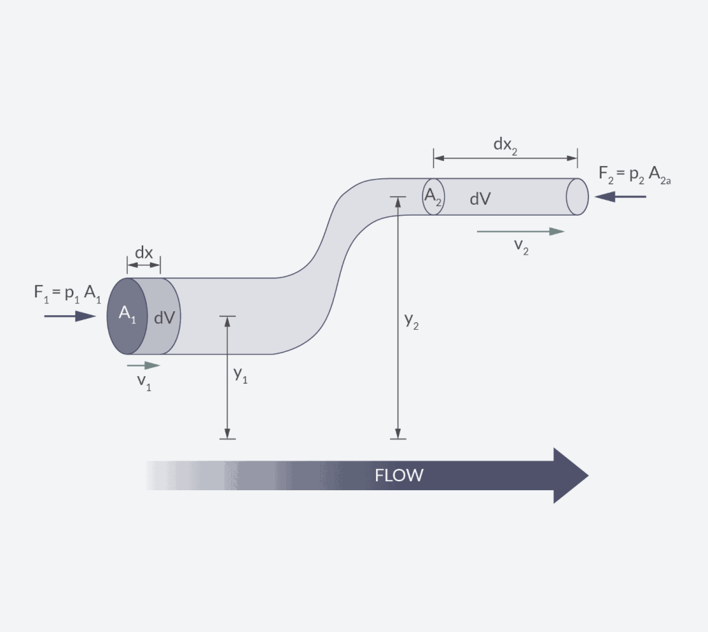
Bernoulli’s equation is based on conservation of energy along a streamline for an ideal fluid:
P + ½ρv² + ρgh = constant.
أين:
- ρgh = potential energy (elevation term)
- P = static pressure
- ½ρv² = kinetic energy (velocity term)
Bernoulli’s equation does not say pressure creates flow. It says energy is redistributed between pressure, velocity, and elevation.
- When velocity increases, static pressure must decrease
- When elevation increases, pressure must decrease
- When velocity decreases, pressure can recover
Engineering Conclusion
- Pressure and velocity are inversely related, not proportional
- High flow velocity often corresponds to low static pressure
- Bernoulli explains phenomena such as:
- Pressure drop at pipe constrictions
- Venturi and orifice flow meters
- Cavitation risk at high velocity points
Darcy–Weisbach Equation — Pressure Loss Due to Friction
In real pipelines, friction dominates the pressure–flow relationship.
This is described by the Darcy–Weisbach equation:
ΔP=f⋅D/L⋅ρv²/2
أين:
- ΔP = pressure drop
- f = friction factor (depends on Reynolds number and pipe roughness)
- L = pipe length
- D = pipe internal diameter
- v = average fluid velocity
Pressure is consumed to overcome resistance caused by:
- Pipe wall friction
- Fluid viscosity
- Turbulence
Unlike Bernoulli, this equation describes irreversible energy loss.
Key Engineering Relationships
From Darcy–Weisbach, several critical conclusions follow:
- Pressure drop increases with velocity squaredΔP∝v2 ΔP∝v2\Delta P \propto v^2
- Pressure drop increases linearly with pipe length
- Doubling the length ≈ doubling pressure loss
- Pressure drop increases dramatically as diameter decreases
- Small diameter reduction → very large ΔP increase
- Higher flow requires disproportionately higher pressure
- Doubling flow may require 3–4× pressure increase (turbulent flow)
Engineering Conclusion
- Pressure does not control flow linearly
- Flow is the result of pressure overcoming friction
- In long or small-diameter pipelines, pressure losses dominate system behavior
- This is why pump and compressor sizing is critical
👉 In most industrial pipelines, Darcy–Weisbach is the governing relationship between flow and pressure.
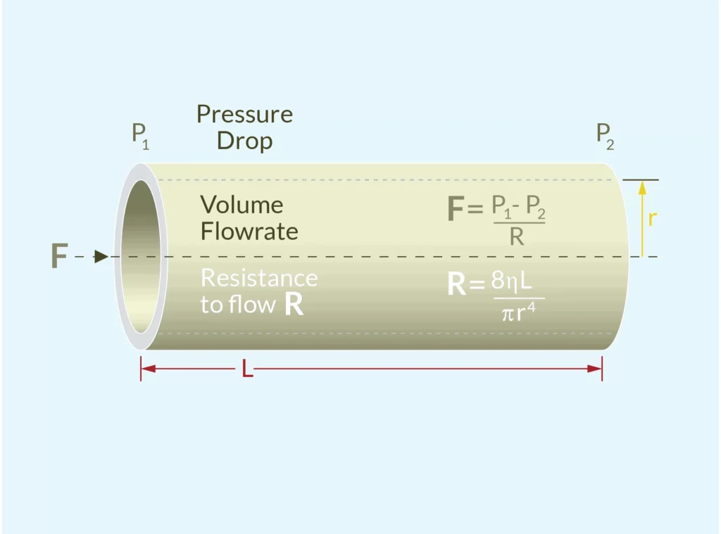
Poiseuille’s Law — Flow vs Pressure in Laminar, Viscous Flow
Poiseuille’s law applies to laminar flow (Reynolds number < 2000), typically seen in:
- Highly viscous fluids (oil, syrup, polymer melts)
- Low flow rates
- Small-diameter pipes or capillaries
The equation is:
Q = π(P₁ – P₂)r⁴ / 8μL.
أين:
- L is the length of the pipe.
- Q is the volumetric flow rate,
- P1 and P2 are the pressures at both ends of the pipe,
- r is the radius of the pipe,
- μ is the viscosity of the fluid,
In laminar flow:
- Fluid layers slide smoothly over each other
- Resistance comes primarily from viscous shear
- Flow responds linearly to pressure
Key Engineering Insights
- Flow is directly proportional to pressure
- Double pressure → double flow
- Flow is inversely proportional to viscosity
- Higher viscosity → much lower flow
- Diameter has an extreme influence (D⁴ relationship)
- A small increase in diameter causes a massive increase in flow
- Reducing diameter slightly can almost stop flow
Engineering Conclusion
- Poiseuille’s law explains why viscous fluids require:
- High pressure
- Large pipe diameters
- Positive displacement or Coriolis flow meters
- It is critical in:
- Oil and lubrication systems, espeically oil flow meter selection.
- Chemical dosing
- Micro-flow and capillary systems
👉 For viscous fluids, diameter matters more than pressure.
How Pressure Really Relates to Flow
From the three principles above, we can summarize:
- Pressure does not “create” flow
- Flow occurs when pressure overcomes resistance
- The pressure–flow relationship depends on:
- Flow regime (laminar vs turbulent)
- اللزوجة
- Pipe diameter and length
One-Sentence Engineering Rule
Flow is not proportional to pressure — it is the result of pressure overcoming friction and viscosity.
Online Calculation Tool
This pipe flow rate calculator calculates the volumetric flow rate (discharge rate) a gas or fluid (liquid) going through a round or rectangular pipe of known dimensions. If the substance is a liquid and its volumetric density is known the calculator will also output the mass flow rate (more information is required to calculate it for gases and it is currently not supported).
In pressure difference mode the calculator requires the input of the pressure before the pipe (or venturi, nozzle, or orifice) as well as at its end, as well as its cross-section, e.g. pressure and diameter for a round pipe. Supported input units include pascals (Pa), bars, atmospheres, pounds per square inch (psi), and more for pressure and kg/m·s, N·s/m2, Pa·s, and cP (centipoise) for dynamic viscosity.
In flow velocity mode one needs to know the flow velocity of the gas or fluid (feet per second, meters per second, km/h, etc. are accepted) in order to calculate the flow rate.