Precise gas flow control is vital in a wide range of industries — from semiconductor manufacturing and chemical processing to food production, environmental monitoring, and fuel cell research. Among the technologies used to manage and monitor gas flow, thermal mass flow controllers (MFCs) stand out for their accuracy, reliability, and ability to provide closed-loop control of mass flow rates.
This blog post explores what thermal mass flow measurement is, how it works, the types of sensors used, and what distinguishes a thermal mass flow controller from a termal kütle akış ölçer. We’ll also look at key benefits, applications, and factors to consider when selecting a thermal MFC.
What is Thermal Mass Flow Measurement?
Thermal mass flow measurement is a direct method for measuring the mass flow rate of a gas based on its thermal properties. Unlike volumetric flow measurement, which measures how much space a gas occupies (which can vary with pressure and temperature), thermal mass flow measures the actual mass of gas molecules moving through a system — a critical distinction in applications where precise control over the quantity of gas, not just its volume, is required.
Basic Principle
The basic operating principle of thermal mass flow measurement relies on ısı transferi: as gas flows past a heated element, it carries away heat. The rate of heat loss is directly proportional to the kütle akış hızı of the gas. The higher the flow, the more heat is carried away.
This allows thermal mass flow devices to offer true mass flow readings, typically measured in units like standard liters per minute (SLPM) veya kilograms per hour (kg/h), without needing external temperature or pressure compensation.
Main Sensor Types in Thermal Mass Flow Measurement
Two primary sensor designs are used in thermal mass flow devices:
1. Capillary Sensor Design
This design is commonly used in low-flow applications and consists of:
- A small-diameter capillary tube through which a portion of the gas is routed.
- Two temperature sensors placed upstream and downstream of a small heater.
- As the gas flows, it transfers heat from the upstream to the downstream sensor, creating a measurable temperature differential.
Capillary designs offer high sensitivity and fast response and are ideal for temiz, kuru gazlar at low flow rates (typically from a few sccm to several slpm).
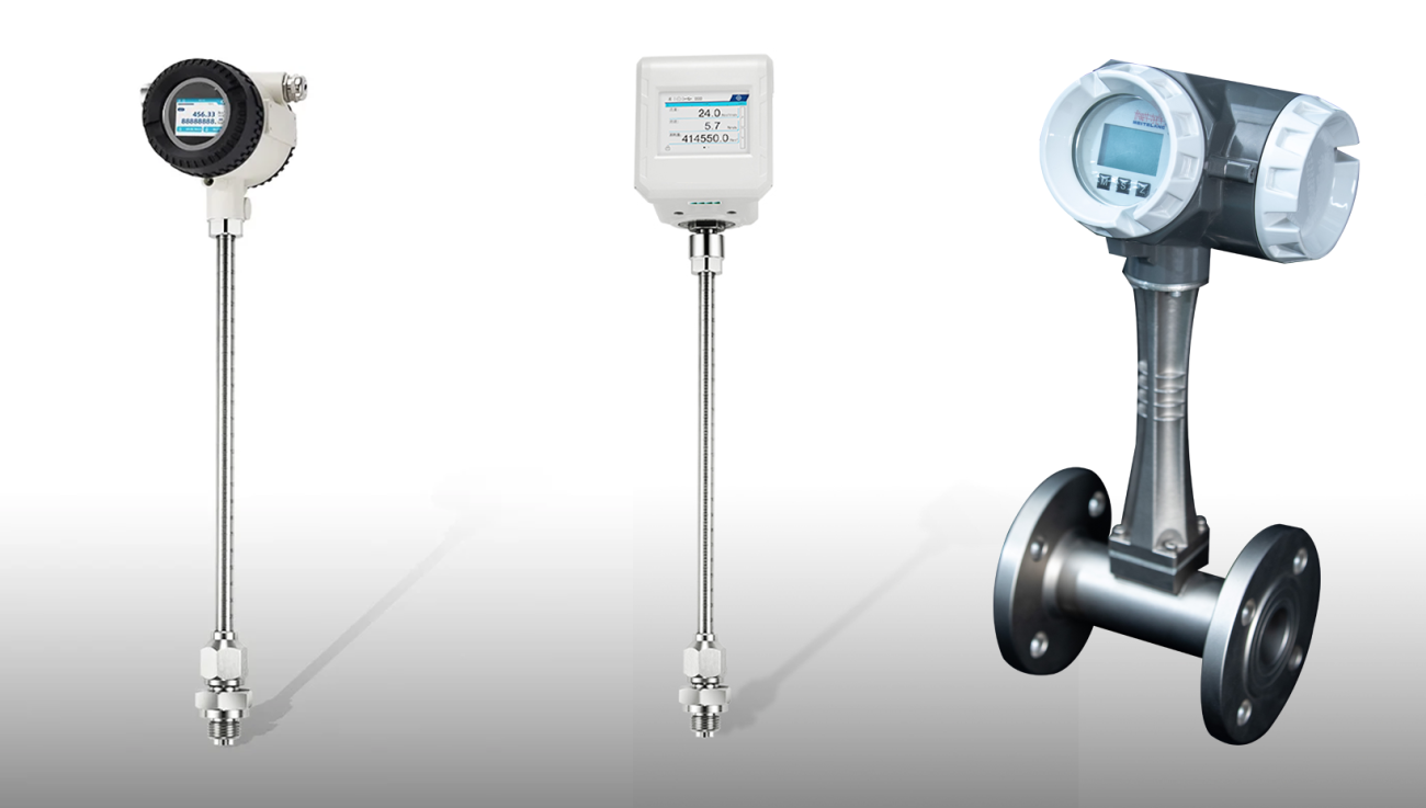
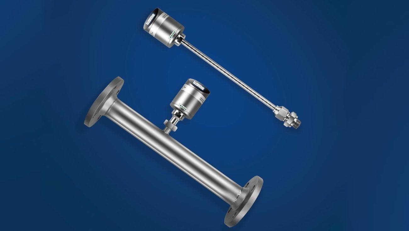
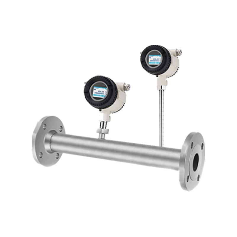
2. Inline or Bypass Sensor Design (MEMS or CTA)
These use either:
- A MEMS (Micro-Electro-Mechanical Systems) sensor integrated into the flow path.
- A Constant Temperature Anemometry (CTA) sensor setup, where the device keeps a heated sensor at a constant temperature relative to ambient.
Inline thermal sensors are suitable for higher flow rates ve larger pipe diameters, often used in industrial or environmental systems.
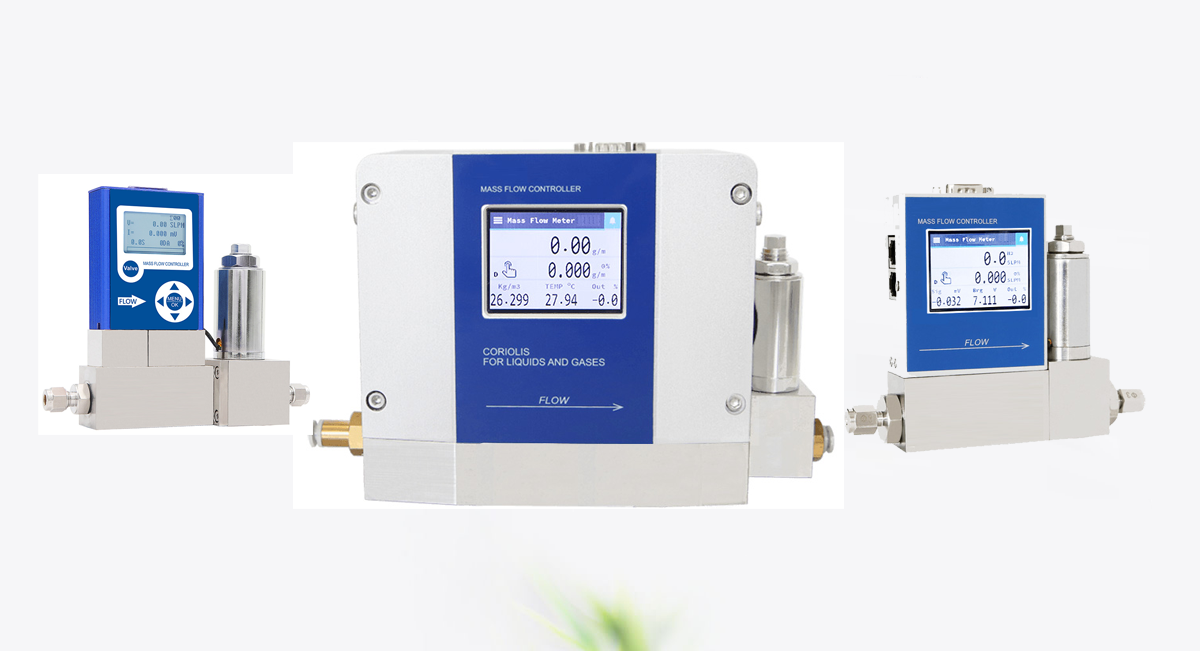
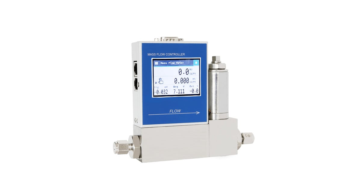
What is a Thermal Mass Flow Controller (MFC)?
A thermal mass flow controller (MFC) is a device that not only measures the mass flow of a gas but also regulates it to a setpoint defined by the user or a control system.
It consists of three main components:
- Thermal Flow Sensor: Measures the actual mass flow rate of the gas in real-time.
- Control Valve (typically solenoid-based or piezoelectric): Modulates gas flow by opening or closing based on feedback from the sensor.
- PID Control Electronics: Compares the measured flow to the setpoint and adjusts the valve position accordingly to maintain constant flow.
Key Characteristics of an MFC:
- Setpoint Input: Accepts an analog signal (e.g., 0-5V, 0-10V, 4-20mA) or digital command specifying the desired flow rate.
- Flow Output: Provides an analog signal (e.g., 0-5V, 4-20mA) proportional to the actual measured flow rate.
- Valve Drive Output: The signal sent to the control valve actuator.
- Control Algorithm: Typically a PID (Proportional-Integral-Derivative) algorithm optimized for fast, stable, and accurate control without overshoot.
- Kalibrasyon: Factory calibrated for specific gases or gas mixtures at defined inlet pressures and temperatures. Accuracy is paramount.
Thermal Mass Flow Meter vs. Flow Controller: What’s the Difference?
While both devices utilize the same core thermal principle for measurement, their purpose and functionality are distinct:
| Feature | Thermal Mass Flow Meter (MFM) | Thermal Mass Flow Controller (MFC) |
|---|---|---|
| Primary Function | Measure the mass flow rate of a gas. | Measure AND Control the mass flow rate of a gas. |
| Temel Bileşenler | Thermal Sensor, Electronics, Flow Output. | Thermal Sensor, Control Valve, Closed-Loop Electronics, Setpoint Input, Flow Output. |
| Output | Signal proportional to measured flow. | Signal proportional to measured flow AND Valve Drive Signal to achieve setpoint. |
| Input | Power, Gas Flow. | Power, Gas Flow, Setpoint Command. |
| Valve? | No. | Yes. Essential for active regulation. |
| Control Loop? | Open Loop. Only reports flow. | Closed Loop. Actively adjusts valve based on error. |
| Analogy | Like a speedometer in a car. | Like cruise control (speedometer + throttle control). |
| Use Case | Monitoring gas consumption, leak detection, process observation. | Precise dosing of reactants, maintaining constant flow for deposition, sputtering, mixing ratios, analytical instrumentation. |
| Complexity & Cost | Generally simpler and lower cost. | More complex due to valve and control loop; higher cost. |
In short: a thermal mass flow meter tells you how much gas is flowing, while a thermal mass flow controller ensures the gas flows at a specific rate.
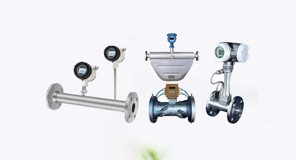
At Metlan Instruments, we offer a full range of thermal mass flow meters and controllers, each engineered for high accuracy, reliability, and customization. Whether you’re designing a new process line or optimizing a laboratory setup, we’re here to help you find the best solution for your flow control needs.
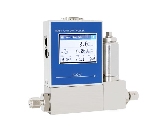
Thermal Mass Flow Controller / Meter:
- Measuring Range: 2SCCM~6000SLM
- Accuracy: ± 0.5% F.S; ± 1% F.S
- Turndown Ratio: Controller: 50:1 | Meter: 100:1
- Working temperature: 0~50℃
- Max. operating pressure: 10MPa
- Connector: φ8,φ10,φ12, flange installation
- Sealing material: Vilton, Neoprene, NBR, metal
- Patlamaya dayanıklılık sınıfı: Ex db IIC T6 Gb / Ex tb IIIC T80°CDb.
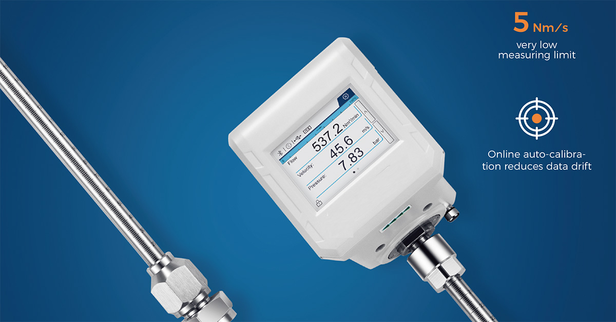
- Measuring Rrange: from 0.1 Nm/s to 250 Nm/s
- Accuracy: Standard: ±(1.5% RD + 0.3% FS) , Optional: ±1% RD
- turndown Ratio: 2500:1
- Medium Temperature Range: -40 to 80°C
- Max. Process Pressure: 63 bar
- Tam dijital sinyal işleme, daha yüksek doğruluk, uzun vadeli kararlılık.
Advantages of Thermal Mass Flow Controllers
Thermal MFCs are widely used for several good reasons:
1. Direct Mass Flow Measurement
They eliminate the need for separate pressure and temperature sensors or compensation algorithms.
2. High Accuracy
Modern thermal MFCs can offer accuracy levels of ±1% of full scale or better, depending on the calibration and gas type.
3. Wide Turndown Ratios
Many MFCs can accurately control flows from 2% to 100% of their rated capacity (50:1 turndown or more).
4. Fast Response Time
Thermal MFCs react quickly to changes in flow demand or control signals, making them ideal for dynamic processes.
5. Compatibility with Clean and Specialty Gases
Thermal technology is particularly suitable for pure or specialty gases used in research, semiconductors, and pharmaceuticals.
Applications of Thermal Mass Flow Controllers
Due to their precision and flexibility, thermal MFCs are used in a wide range of industries and systems:
- Semiconductor Manufacturing: Critical for CVD (Chemical Vapor Deposition), Etching, Epitaxy, Ion Implantation, and Sputtering. Precise control of dopant gases, precursors, and etchants directly impacts film thickness, uniformity, and device performance.
- Pharmaceutical & Biotechnology: Fermentation control (O₂, CO₂, N₂), bioreactor sparging, catalyst research, controlled atmosphere systems (incubators), precise dosing in drug synthesis and formulation.
- Analytical Instruments: Calibrating and supplying carrier gas, reagent gases, and make-up gases for GC (Gas Chromatography), MS (Mass Spectrometry), FTIR, and other lab equipment requiring ultra-stable flows.
- Fuel Cell & Battery Research: Controlling reactant gases (H₂, O₂) and purge gases (N₂) during testing and operation.
- Environmental & Emissions Monitoring: Calibrating gas analyzers, controlling dilution ratios for sampling systems.
- Additive Manufacturing (3D Printing): Controlling shielding gases (Ar, N₂) and reactive gases in metal printing processes like DMLS/SLM.
- Laser Cutting & Welding: Precise control of assist gases (O₂, N₂, Ar) to optimize cut quality and speed.
- Combustion & Process Optimization: Tuning fuel-to-air ratios (e.g., natural gas, biogas) in burners for maximum efficiency and minimal emissions.
Key Selection Criteria for Thermal MFCs
When choosing a thermal mass flow controller, consider the following factors:
1. Gas Type
Each MFC is calibrated for a specific gas. Using it with a different gas requires correction factors or recalibration.
2. Akış Aralığı
Define the minimum and maximum flow rates required. A 50-100% range is ideal for optimal accuracy.
3. Accuracy & Repeatability
Higher-precision applications (e.g., lab or R&D) require better specs than general industrial applications.
4. Pressure & Temperature Conditions
Ensure the controller is rated for your operating conditions, especially for pressurized gas delivery systems.
5. Control Interface
Analog (0-5V, 4-20mA) or digital (RS-485, Modbus, Profibus, EtherCAT) — choose one that integrates with your control system.
6. Valve Type
Solenoid valves are standard, but piezoelectric valves offer better resolution and lower power consumption in some applications.