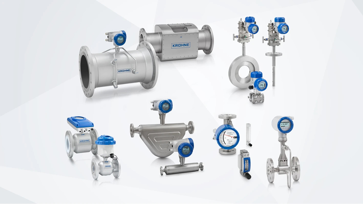
Flow meters are specialized instruments used to measure fluid flow, widely applied across industrial and scientific fields. This article provides an animated demonstration and brief descriptions of the working principles of 11 commonly used industrial flow meters. These devices leverage principles from mechanics, electricity, thermodynamics, and other disciplines, offering critical technical support for industrial production and scientific research.
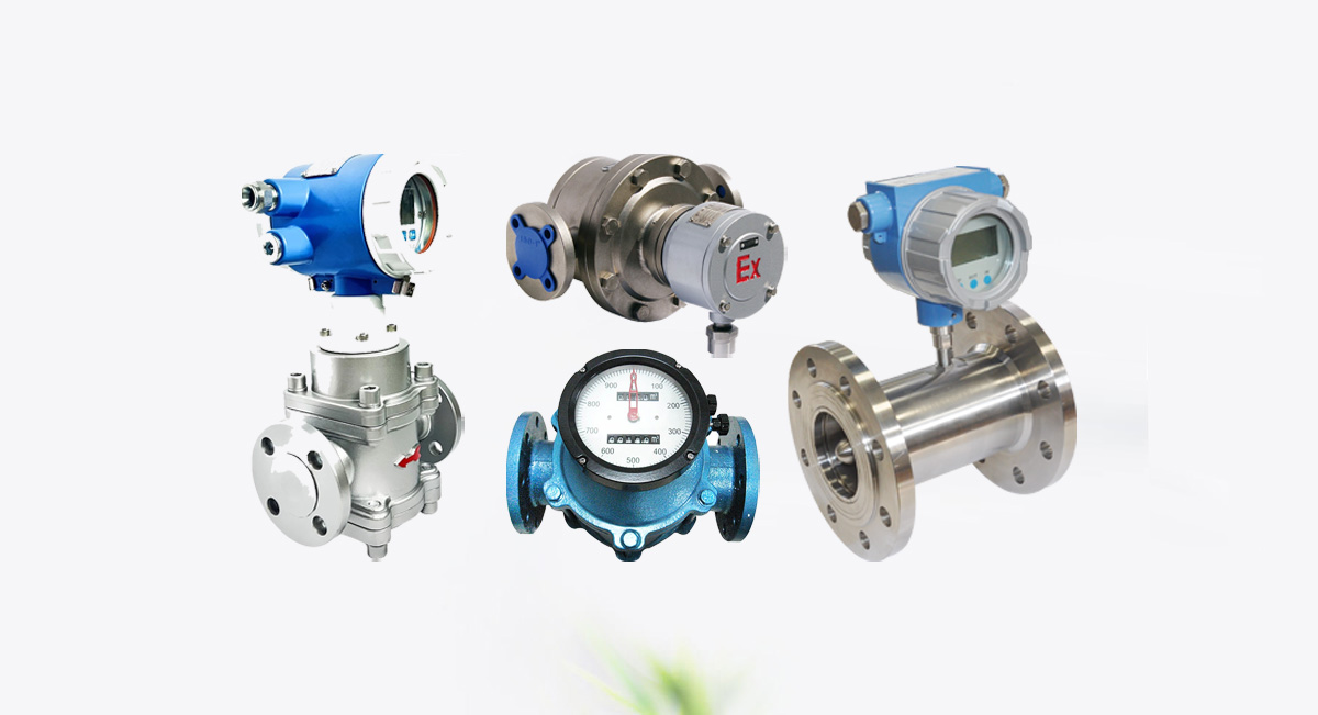
1. Turbine Flow Meter
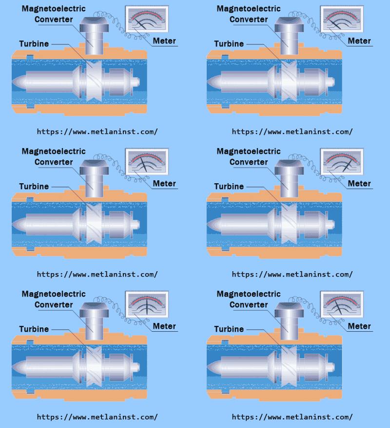
The rotational speed of the turbine is directly proportional to the fluid flow velocity within a specific range. As the fluid flows, it drives the turbine to rotate. The rotational speed is converted into electrical pulse signals, which are displayed on a secondary instrument, accurately reflecting the fluid flow rate.
2. Rotameter (Variable Area Flow Meter)
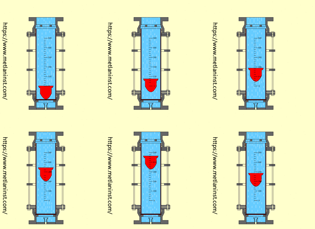
The fluid enters the conical tube from the bottom, pushing the float upward. The float is subjected to dynamic pressure from the upward flow, buoyancy due to the displaced fluid, and the downward gravitational force from its own weight. As the flow rate changes, the forces acting on the float adjust accordingly. When these forces reach equilibrium, the float stabilizes at a specific position within the tube. For a given design, the float’s position corresponds to a specific flow rate, as calibrated by the tube’s scale or electronic measurement system. This allows the flow rate to be read directly, providing a reliable and accurate method for continuous flow monitoring.
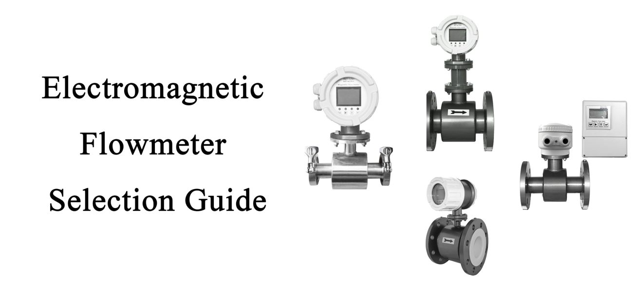
3. Electromagnetic Flow Meter
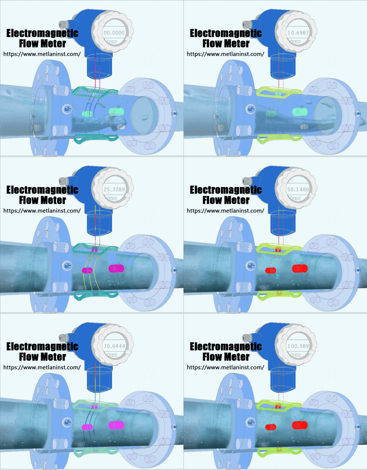
Electromagnetic flow meters operate on Faraday’s law of electromagnetic induction, where a voltage proportional to the flow velocity is induced as a conductive fluid moves through a magnetic field. Electrodes detect this voltage, which the transmitter processes to determine the volumetric flow rate. With no moving parts, these meters are highly reliable, low-maintenance, and ideal for conductive liquids like water, wastewater, and corrosive fluids, offering versatility and durability in various industrial applications.
4. Vortex Flow Meter
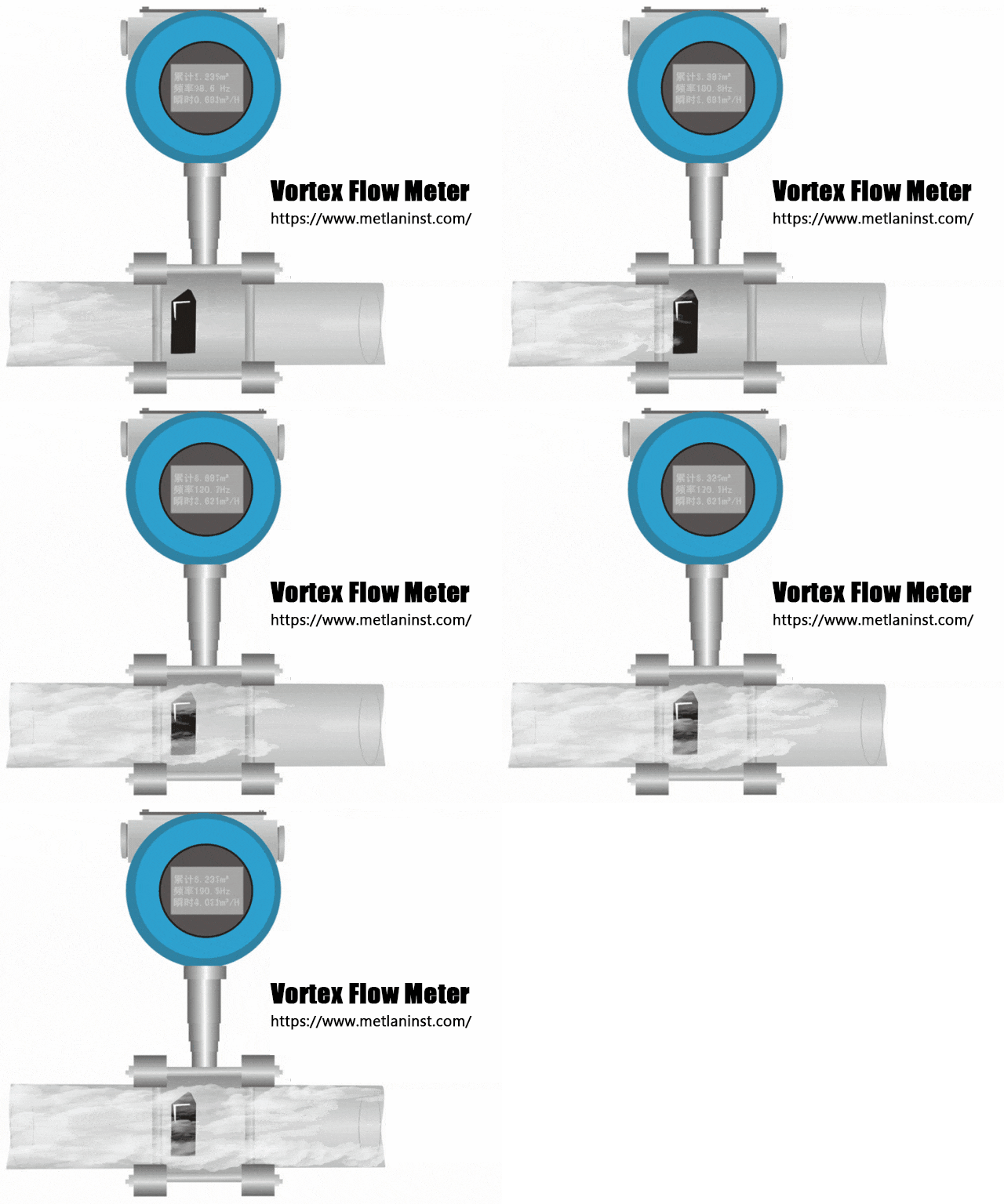
Vortex flow meters use the principle of fluid oscillation. When fluid passes a bluff body in the meter, alternating vortices are generated downstream, with a frequency proportional to the fluid velocity. By measuring the vortex frequency and considering the pipe cross-sectional area, the flow rate is calculated. This simple and reliable method is widely used.
5. Coriolis Mass Flow Meter
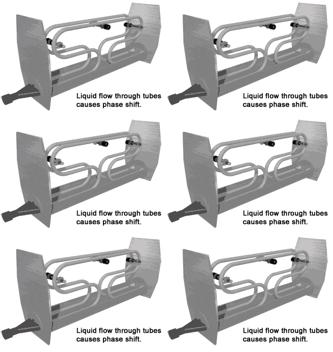
Based on the Coriolis effect, fluid flowing through a vibrating tube generates a force proportional to the mass flow rate. By measuring this force, the Coriolis flow meter directly and accurately determines the mass flow. It is widely used in precision industrial applications.
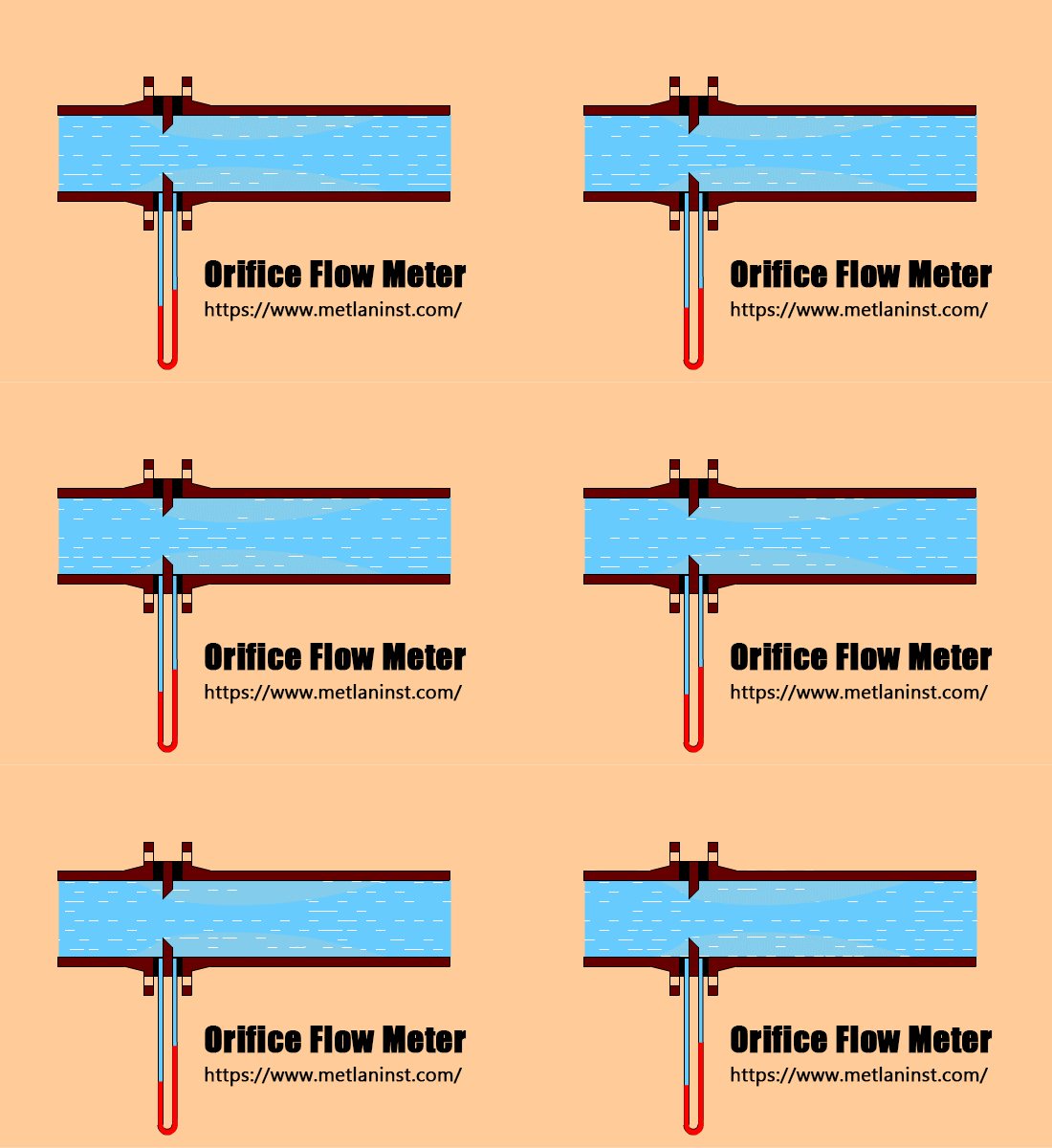
6. Orifice Flow Meter
When fluid flows through an orifice plate, it accelerates while the static pressure decreases, creating a pressure difference between the upstream and downstream sides. Based on the principle of energy conservation, the flow rate is directly proportional to this pressure difference. Orifice flow meters are cost-effective and suitable for various media.
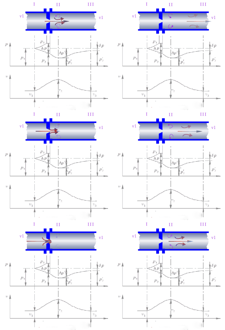
7. Nozzle Flow Meter
As fluid passes through the nozzle, its velocity increases while static pressure decreases, creating a pressure difference. The flow rate is proportional to this pressure difference. By measuring the pressure difference, the flow rate is accurately determined. Nozzle flow meters are reliable and suitable for high-speed, high-pressure conditions.
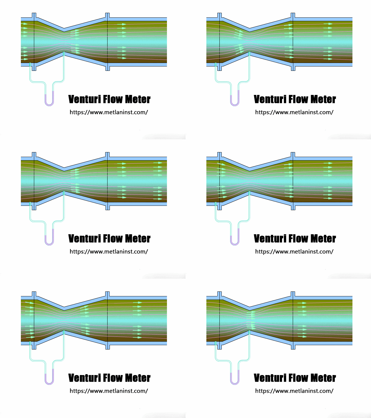
8. Venturi Flow Meter
As fluid flows through the constriction of a Venturi tube, its velocity increases and static pressure decreases, creating a pressure differential. The pressure difference correlates with the flow rate. Venturi flow meters have low pressure loss and are suitable for measuring large flows.
9. Ultrasonic Flow Meter
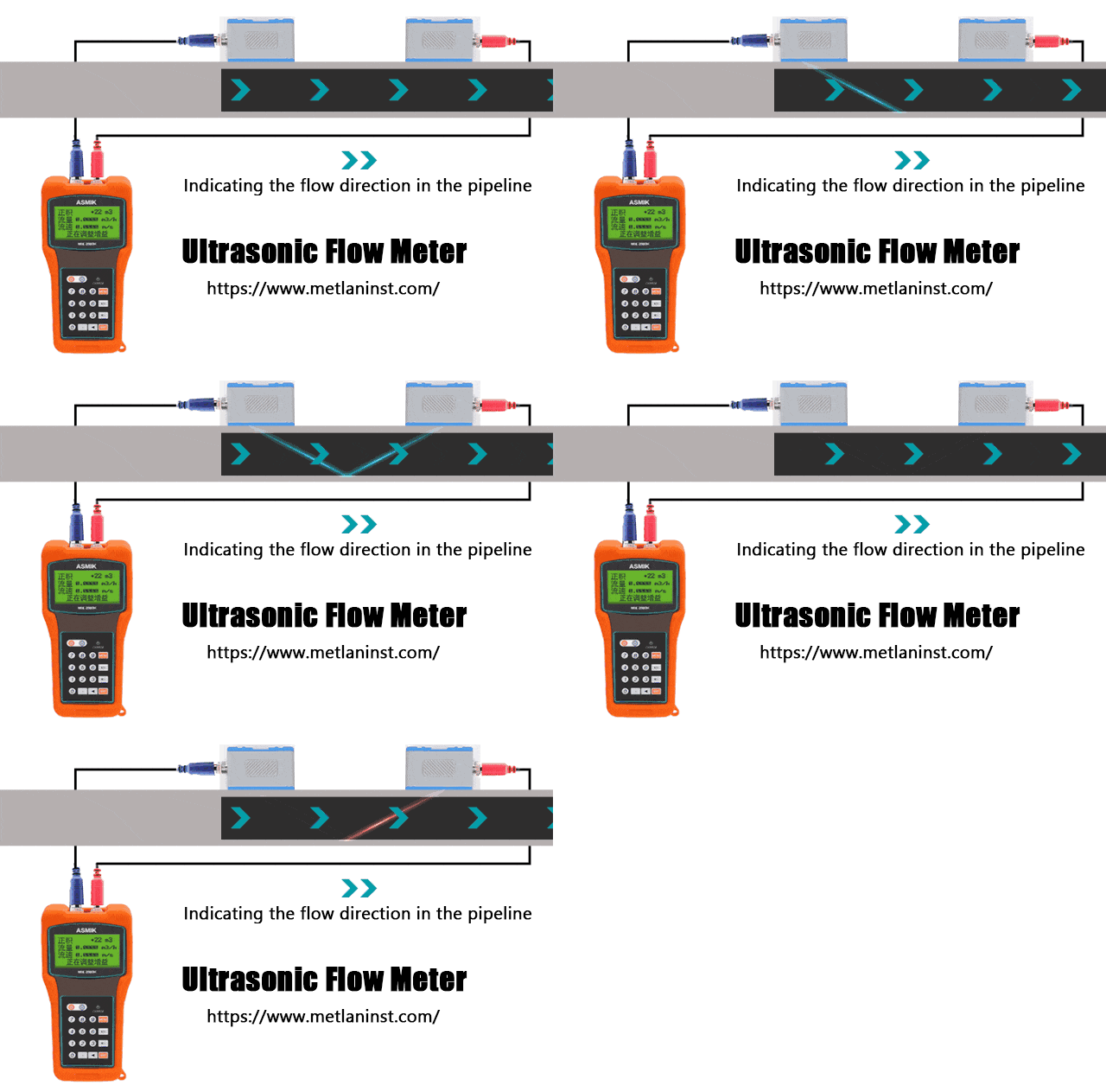
Ultrasonic flow meters often use the “time difference method,” where two transducers transmit ultrasonic signals across the fluid. The difference in travel time between upstream and downstream signals is used to calculate fluid velocity and flow rate. This non-invasive, high-accuracy method is versatile and widely applicable.
10. Positive Displacement Flow Meter
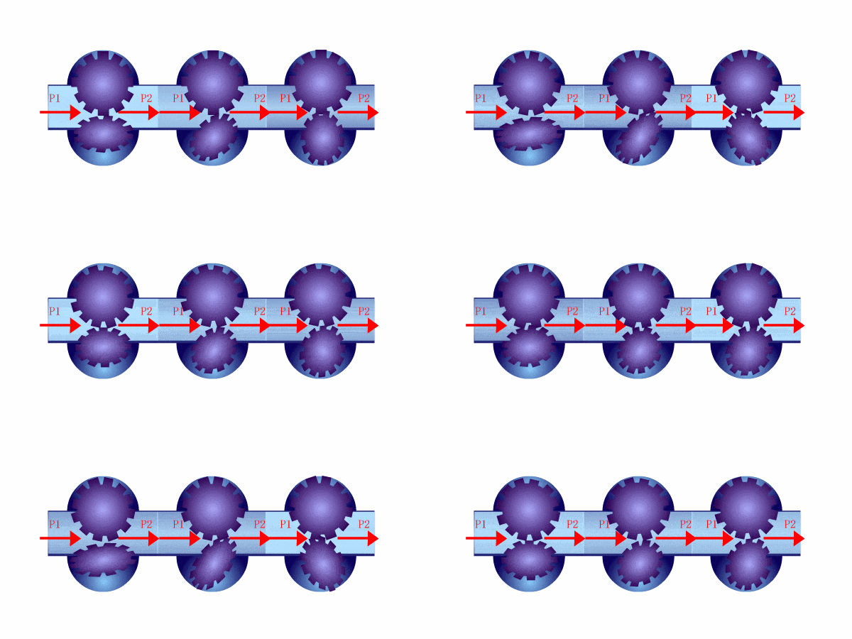
Driven by the pressure difference between the inlet and outlet, rotors within the flow meter rotate, causing fluid to fill and discharge fixed-volume chambers. By counting the number of rotor rotations, the total volume of fluid passing through the meter can be directly calculated. This method is highly accurate and ideal for high-viscosity liquids.
11. Oval Gear Flow Meter
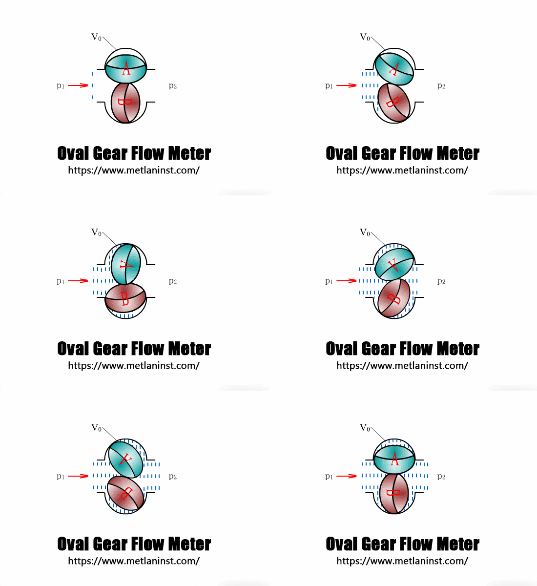
Pressure difference drives a pair of oval gears to rotate continuously, measuring and transferring liquid from the crescent-shaped cavity to the outlet. The total flow is directly proportional to the number of gear rotations multiplied by the volume per rotation. This meter is effective for high-viscosity liquid flow measurement.
Conclusion
The 11 flow meters introduced in this article encompass principles from mechanics, electricity, and thermodynamics, with extensive applications in industrial and scientific flow measurement. Understanding their working principles can help select the most suitable flow meter for specific needs, improving measurement accuracy and operational efficiency.

Leave a comment